

Calibration Reference Files and Tables
Table 6.4 summarizes the FOS calibration parameters needed by RSDP. For each parameter, the table lists the STSDAS tasks that generates the parameter, and the name of the CDBS relation (if any) in which the parameter is stored.

FOS Calibration Parameters Required by RSDP
Raw counts are converted to count rates by dividing each data point by the exposure time and correcting for disabled diodes. If the science data header keyword DEFDDTBL is true, then the disabled diodes are taken from the Unique Data Log (UDL), otherwise, disabled diodes are found in the file specified in the keyword DDTHFILE. This file is selected from the reference relation CYDDTR.
Count rates are corrected for the geomagnetically-induced image motion problem (GIMP). GIMP-correction scale factors (table CCS7) are used to shift the spectrum in the FOS X-direction to correct for the effects of the Earth's magnetic field on the FOS detector. Offsets are based on model calculations of the Earth's magnetic field at the position of the telescope at the time of the observation. This correction is not necessary for observations that were obtained using the on-board GIMP correction scheme (which became available in April 1993).
Raw count rates are corrected for saturation in the detector electronics. Dead time constants (table CCG2) are used to correct for the nonlinear response of each diode. These constants are not expected to change through the lifetime of the instrument. Analysis of prelaunch data indicate that the same constants can be used for both FOS detectors.
The background can be subtracted from the sky and object spectra. If no background was taken, a default reference background, indicated by the keyword BACHFILE, is used. The observed background is smoothed with a median, followed by a mean filter, before subtraction. Filter widths are stored in table CCS3. No smoothing is done to the reference file background, if used. The reference background may, however, be scaled (using table CCS8) according to the geomagnetic position of the telescope at the time of the observation. The default background file is selected from the reference relation CYBACR.
Diode-to-diode sensitivity variations and fine structure are removed by multiplying by the flat field response. This process requires the flat field response file given by the keyword FL1HFILE. A second flat field file, FL2HFILE, is required for paired-aperture or spectropolarimetry observations. These files are selected from the reference relation CYFLTR.
The sky spectrum, if observed, can be subtracted from the object spectra. The emission line relation (CCS2) gives regions where a sky spectrum should not be smoothed before subtraction from the object spectrum. The filter parameters table (CCS3) contains the filter widths (mean and median) for smoothing the sky (or background) spectra. The sky shift parameter (CCS5) gives an integer shift--in pixels--that is to be applied to the sky spectrum before subtraction. The aperture parameters (CCS0) contain aperture areas required to scale a sky spectrum taken in one aperture of a paired aperture before subtraction from the object spectrum taken in the other aperture. Values for this relation are required only for the paired apertures. The aperture position parameters (CCS1) are used to determine which aperture (UPPER or LOWER) of an aperture pair, was used for observing an object or sky spectrum.
The wavelength parameters (CCS6) give the dispersion coefficients used to generate wavelength scales. Separate coefficients are required for each detector, disperser, aperture, and polarizer mode.
Object spectra are converted to absolute flux units by multiplying by the inverse sensitivity vector. This step requires the inverse sensitivity file found in header keyword IV1HFILE. A second inverse sensitivity file, IV2HFILE, is required for paired-aperture or spectropolarimetry observations. These files are selected from the reference relation CYIVSR.
The final step performs ground software mode dependent reductions for time-resolved, spectropolarimetry, and rapid-readout observations. The spectropolarimetry reductions require the Wollaston and Waveplate parameter table, CCS4, and the retardation reference file, RETHFILE. The retardation file is selected from the reference relation CYRETR.
The calibration process is controlled by the values of certain header keywords. These keywords may be examined and modified using the task chcalpar.
The later versions of calfos (version 1.2.3 and later) are not backwards compatible with all FOS header formats. In this case, the task newfoshdrs can be used to transform the old headers to an acceptable format for running calfos. Please note, that some additional header changes may be needed to get calfos to run to completion.
FOS Calibration Parameters (Non-RSDP)
Y-bases are the Y positions required to center a spectrum on the diode array for any detector, disperser, aperture, and polarizer mode. These must be closely monitored as they affect the quality of the scientific data. Improper Y-bases will decrease the amount of flux recorded by the diode array.
The detector discriminator values are computed by the phay task, which fits a Gaussian function with a polynomial baseline to the differential pulse height distribution.
The aperlocy and apscale tasks are used to analyze FOS target acquisition images.
FOS Display and Analysis Tasks
Generated with WebMaker
RSDP Calibration Code--calfos
The calibration process consists of the following steps:
The propagated error is calculated at each point in the spectrum. This is done by first calculating the statistical errors of the raw data (as the square root of the raw counts per pixel). The error spectrum is then processed in lock-step with the science spectrum throughout the remaining steps of the calibration process. Observation Planning and Instrument Configuration
In addition to the calibration parameters needed by RSDP, there are other FOS calibration parameters that are needed to configure the instruments, and compute target acquisition parameters. These additional parameters are described in Table 6.5.
Data Reduction and Display
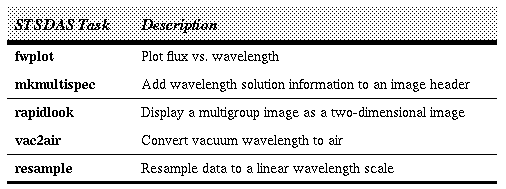
The tasks listed in Table 6.6 are used to display or prepare the data for further analysis.


