Author: Warren Hack, Andy Fruchter, Perry Greenfield, Nadezhda Dencheva
Date: 12 Oct 2010
Abstract
A convention for storing distortion information in HST images was developed and implemented in two software packages - PyWCS and STWCS. These changes allow the development of a WCS based version of Multidrizzle and image alignment software. The distribution of WCS solutions is discussed.
Calibration of the HST Advanced Camera for Surveys (HST/ACS) distortion requires the use of several components to the distortion correction; namely, polynomial coefficients, a lookup table for non-polynomial terms, a time-dependent skew, and a detector defect correction. Each of these terms has been derived as part of the calibration effort to address separate aspects of the distortion that affects ACS observations. Ideally, each would be applied independently in the same manner used for deriving the original calibration reference information, with the time-dependent skew being folded into the other terms. However, the software for applying the distortion models does not support this option. In fact, there is no clear accepted standard for specifying distortion corrections in FITS headers. Instead, there are several separate proposals for specifying aspects of the distortion, but none by themselves allows us to fully specify the distortion already calibrated for ACS, let alone in a modular, efficient manner.
This paper describes a composite implementation of a select set of proposed standards which supports all aspects of the distortion models for HST instruments without breaking any of the conventions/standards. The rules for merging the proposed standards allow software to be defined to apply each aspect of this proposal as a separate option while defining the requirements necessary to allow them to work together when specified in the header. As a result, the separate components essentially become tools where only those conventions appropriate to the observation can be used as needed.
All calibrations for HST observations get recorded and applied through the use of reference files, separate files which describe some calibration. The geometric distortion typically applied to HST images gets recorded as a polynomial component in one reference file, and a pixel-by-pixel correction to the polynomial solution in a separate reference file. This method allows the distortion to be corrected to an accuracy of better than 0.1 pixels. However, this method requires the user to obtain the reference files themselves anytime they want to reprocess the data. The size of these reference files (up to 200Mb) makes this an expensive requirement for the end user. The alternative would be to include the necessary specification of the distortion model in the header of the image itself, as long as it can be done in a manner that does not dramatically increase the size of the image itself. For reference, a typical calibrated ACS/WFC image requires a 168Mb file. Thus, we needed an alternative to separate reference files which can be implemented in a very efficient manner within the image’s FITS headers.
The calibrations also represent separate aspects of the detector and the distortion, aspects which logically should remain as separate descriptions in the header. The pixels for each CCD do not have the same size across the entire chip. The ACS/WFC CCDs manufacturing process resulted in the pixels having different sizes every 68.3 columns, and can be represented most efficiently and accurately by a 1-D correction that gets applied to every row in the chip. This detector level characterization affects all images readout from the CCD regardless of any additional distortion applied to the field of view. Logically, this effect should be kept as a separate component of the distortion model that gets applied prior to correcting for any other distortion. This represents an example of an effect that is best applied sequentially to the image data.
Additional distortions come as a result of the effect of the optics on the field of view. These are generally described by low-order polynomials for most instruments, although for ACS, an additional non-polynomial correction needed to be taken into account as well. Fortunately, the non-polynomial correction can sub-sampled enough to make it practical to include in the image headers directly, a correction of up to a quarter of a pixel in some areas of the detector. Both components need to be applied to the data in order to align images well enough for subsequent data analysis or cosmic-ray rejection.
These corrections could be combined into a single look-up table, yet it would come at the cost of additional errors which may not allow the remaining data analysis or cosmic-ray rejection to actually succeed. We also have some instruments where there is only a polynomial component, requiring the development of support for a polynomial correction and a look-up table anyway.
These requirements on the application of the calibrations to HST data leave us with no alternative within current FITS standards. As a result, we developed this set of rules which allow us to take advantage of the most appropriate conventions for each separate component of the distortion model and combine them in an efficient manner which eliminates the need for external reference data.
Current implementations of distortion models in FITS headers have been limited to simply describing polynomial models. The prime example of this would be the implementation of SIP in WCSTOOLS and DS9 as used for Spitzer data. The keywords used for the SIP standard are:
CTYPE1  = 'RA---TAN-SIP'
CTYPE2  = 'DEC--TAN-SIP'
CDi_j          / Linear terms of distortion plus scale and orientation
A_ORDER =   n  / polynomial order, axis 1, detector to sky
A_i_j          / High order coefficients for X axis
A_DMAX = 0.0   / [pixel] maximum correction along axis 1
B_ORDER =   m  /  polynomial order, axis 2, detector to sky
B_i_j          / High order coefficients for axis 2
B_DMAX = 0.0   / [pixel] maximum correction along axis 2
SIPREFi = 0.0  / Origin of distortion model along axis i
SIPSCLi = 1.0  / Scale term for axis i
The SIP convention retains the use of the current definition of the CD matrix where the linear terms of the distortion model are folded in with the orientation and scale at the reference point for each chip to provide the best linear approximation to the distortion available. The SIP convention gets applied to the input pixel positions by applying the higher-order coefficients A_i_j, B_i_j, then by applying the CD matrix and adding the CRVAL position to get the final world coordinates.
This convention was created from the original form of the FITS Paper IV standards, but the Paper IV proposal since changed to use a different set of keywords and conventions.
The current Paper IV conventions provide a mechanism for specifying either a lookup table or polynomial model for the distortion of each axis. The standard states in Section 2.1:
Note that the prior distortion functions,, operate on pixel coordinates (i.e. p rather than p− r ), and that the independent variables of the distortion functions are the uncorrected pixel or intermediate pixel coordinates. That is, for example, we do not allow the possibility of
The keywords used for describing these corrections use the syntax given in Table 2 of Paper IV. For our purposes, the keywords of interest are those related to lookup tables; namely,
CPDISja        string    2.4.1 distortion code new Prior distortion function type.
DPja           record   2.4.2 distortion parameter new Parameter for a prior distortion function, for use in an image heade
This syntax only provides the option to specify one correction at a time for each axis of the image. This precludes being able to use this convention to specify both a lookup table and a polynomial model at the same time for the same axis. It does not state what should be done if the polynomial has been specified using a different convention, for example, the SIP convention. Thus, SIP and Paper IV should not be seen as mutually exclusive. In fact, they may work together rather naturally since the SIP and Paper IV conventions both assume the corrections will work on the input pixel and add to the output frame.
The reference file to be used for this correction will not have the same format as the original DGEOFILE as used by ACS and WFPC2 as that large of a reference file would more than double the size of each input image since the reference file gets folded into each file. Instead, a sub-sampled array of corrections will be stored in the new reference file, with ACS using a 65 x 33 array for each ACS/WFC chip. This new reference file will be called an NPOLFILE in the FITS image header, so that any original DGEOFILE reference filename can be retained in parallel for backwards compatibility with the current software. This reference file will also have a unique suffix, _npl.fits, as another means of identifying it as a new r eference file separate from the current DGEOFILE files. The header for this new reference file also remains very simple, as illustrated in Appendix 1.
The two 65 x 33 arrays get read into memory with each input ACS/WFC chip (one for X offsets and one for Y offsets). Bi-linear interpolation based on the input pixel position then gets used on-the-fly to extract the final offset from this reference file. Initial versions of these sub-sampled NPOLFILE reference files for ACS have been derived from the current full-size DGEOFILEs, but testing indicates residuals on the order of 0.02 pixels remain when compared to Jay’s results.
The last element of the distortion which remains to be described is the fixed column (or row) width correction. This needs to be applied as a correction to the input pixel position and the output of this correction is to be used as input to the polynomial and non-polynomial distortion corrections.
The adopted implementation is based on Paper IV Lookup Table convention. It is assumed that the detector to image correction is the same for all chips but it can be extended to arbitrary number of chips and extensions if necessary.
For ACS the correction is stored as an image extension with one row. Each element in the row specifies the correction in pixels for every pixel in the column (or row) in the science extension as predetermined by the calibration teams who would be responsible for creating the reference files. For ACS the correction is in the X direction and for WFPC2 - in the Y direction. The following new keywords are added to the primary header of a science file:
'D2IMFILE' = "string - name of reference file to be used for creating the lookup table"
'AXISCORR' = "integer (1 or 2) - axis to which the det2im correction is applied"
'D2IMEXT' = "string - name of reference file which was last used to create the lookup table"
'D2IMERR' = (optional)" float - maximum value of the correction"
‘D2IMFILE’ is used by UPDATEWCS as a flag that a reference file with this correction exists and an extension should be created. UPDATEWCS records the name of the reference file used for the lookup table extension to a keyword D2IMEXT in the primary header. It also populates keyword ‘AXISCORR’ based on whether this is a row or column correction. The lookup table extension has an ‘EXTNAME’ value of ‘D2IMARR’.
‘AXISCORR’ is used as an indication of the axis to which the correction should be applied (1 - ‘X’ Axis, 2- ‘Y’ axis). ‘D2IMEXT’ stores the name of the reference file used by UPDATEWCS to create a D2IMARR extension. If ‘D2IMEXT’ is present in the ‘SCI’ extension header and is different from the current value of D2IMFILe in the primary header, the correction array in D2IMARR is updated. The optional keyword ‘D2IMERR’ allows a user to ignore this correction without modifying other header keywords by passing a parameter to the software. The HSTWCS class accepts a parameter ‘minerr’ which specifies the minimum value a distortion correction must have in order to be applied. If ‘minerr’ is larger than ‘D2IMERR’ the correction is not applied.
An entirely new reference file needs to be generated in order to specify this correction for each affected instrument. This reference file only contains a single array of offsets corresponding to the 1-D correction to be applied. Header keywords in the reference file then specify what axis gets this correction. As a result, this new reference file remains small enough to easily be added to an input image without significant change in size. An initial D2IMFILE for ACS has been generated for testing with a sample header provided in the Appendix.
The WCS for this correction describes the extension as a 1-D image, even though it will be applied to a 2-D image. This keeps it clear that the same correction gets applied to all rows(columns) without interpolation. The header specifies which axis this correction applies to through the use of the AXISCORR keyword. The WCS keywords in the header of the D2IMARR extension specifies the transformation between pixel coordinates and lookup table position as if the lookup table were an image itself with 1-based positions (starting pixel is at a position of (1,1)). The value at that lookup table position then gets used to correct the original input pixel position.
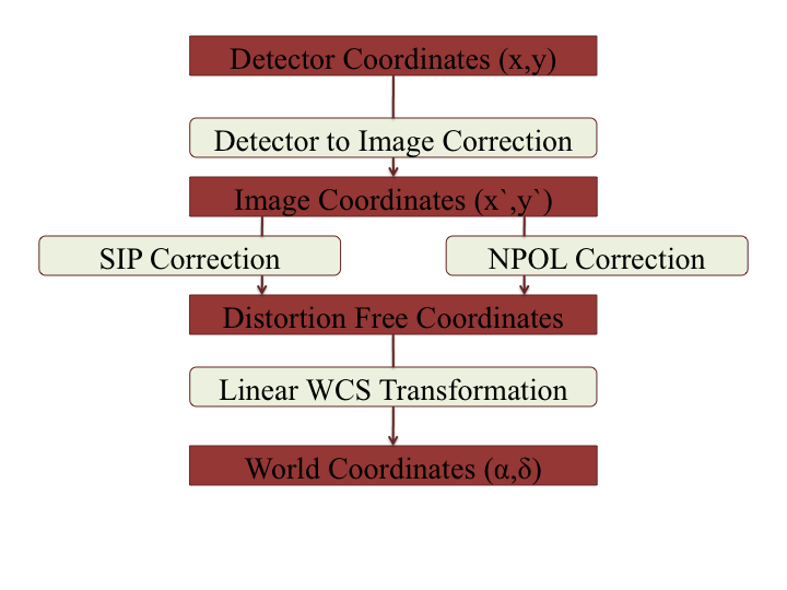
The full implementation of all these elements ends up merging the SIP, DET2IM and Paper IV conventions to create a new version of the figure from Paper IV which illustrates the conversion of detector coordinates to world coordinates. This implementation works in the following way:
- Apply detector to image correction (DET2IM) to input pixel values
- Apply SIP coefficients to DET2IM-corrected pixel values
- Apply lookup table correction to DET2IM-corrected pixel values
- Add the results of the SIP and lookup table corrections
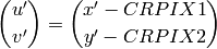
- Apply the WCS transformation in the CD matrix to the summed results to get the intermediate world coordinates
- Add the CRVAL keyword values to the transformed positions to get the final world coordinates
The computations to perform these steps can be described approximately using:


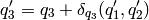
where f(u’,v’) and g(u’,v’) represent the polynomial distortion correction specified as
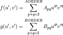
where
 is the residual distortion in the lookup tables
written to the header using the Paper IV lookup table convention
is the residual distortion in the lookup tables
written to the header using the Paper IV lookup table conventionThese equations do not take into account the deprojection from the tangent plane to sky coordinates. The complete Detector To Sky Coordinate Transformation is based on the CTYPE keyword.
Coordinate Transformation Pipeline