

Calibration Reference Files and Tables
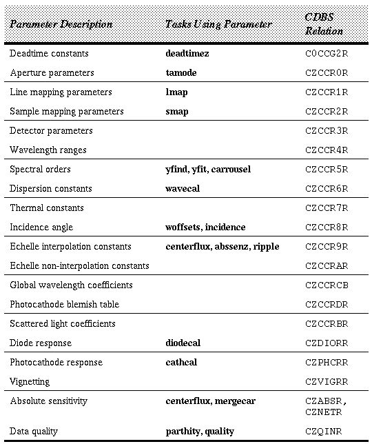
Table 6.7 describes the GHRS calibration parameters used in the pipeline. For each parameter, the table lists the STSDAS tasks that generate the parameter, and the name of the CDBS relation (if any) in which the data are stored.

Pipeline Calibration Parameters for GHRS
Diode non-linearities are removed by applying a paired-pulse or deadtime correction using coefficients stored in the table CCG2. The non-uniformities are then removed by dividing by the diode response for each diode (or an average response if comb-addition is used), stored in reference file DIOHFILE. DIOHFILE contains 512 responses (one per diode) and is selected by detector.
Photocathode granularities are removed by first mapping each data point from detector coordinates (diode and deflections) to photocathode coordinates (line and sample) using coefficients in tables CCR1 and CCR2. The photocathode response is then obtained from the reference file PHCHFILE, which contains a response grid organized by line and sample. The reference file PHCHFILE is selected by grating mode.
Vignetting correction corrects light loss caused by both vignetting and low-frequency sensitivity variations across the photocathode. The vignetting file, VIGHFILE, is selected by grating mode, and has values tabulated as a function of carrousel position, line position, and sample position.
Wavelengths are determined for each point by solving the dispersion equation relating photocathode sample position to wavelength and spectral order. For the first-order gratings, the spectral order is defined as 1. For the Echelle spectra, the spectral order is computed from the Y-deflection and carrousel position, using parameters in table CCR5. The dispersion coefficients are found in table CCR6 and are corrected for thermal effects using coefficients in table CCR7. If the object is in the large science aperture, an incidence angle offset is added to the wavelengths. The offset is computed using coefficients stored in table CCR8. A velocity correction is done to convert to heliocentric wavelengths and finally, a vacuum-to-air correction is performed for wavelengths above 2000 Å.
The background is smoothed by a median and a mean filter (with widths specified in table CCR3, or a low-order polynomial (with order specified in table CCR3). If the background is a sky spectrum (as specified by its substep bin ID), it is normalized to the object spectrum aperture using aperture sizes stored in table CCR0 before being subtracted from the entire spectrum. Contributions from scattered light are calculated using coefficients found in table CCRB and are subtracted with the background.
A ripple correction is performed for data taken with an Echelle mode using coefficients in tables CCR9 and CCRA.
The net flux is then converted to absolute flux units using the sensitivity tables stored in reference files ABSHFILE and NETHFILE.
The calibration process is controlled by the values of certain header keywords. These keywords may be examined and modified using the task chcalpar.
The later versions of calhrs (version 1.2.3 and later) are not backwards compatible with all GHRS header formats. In this case, the task newhrshdrs can be used to transform the old headers to an acceptable format for running calhrs. Please note, that some additional header changes may be needed to get calhrs to run to completion.
Other GHRS Calibration Parameters
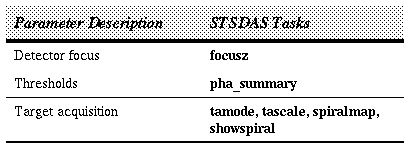
The GHRS detector focus is measured by the focusz task as the distance (in deflection units) from the 10% to the 90% level of the photocathode edge profile.
The detector thresholds are computed by phaz by fitting a Gaussian function with a linear baseline to the differential pulse height distribution. The position of the Gaussian is used to set an optimal threshold for each diode.
The tamode and tascale tasks are used to analyze GHRS field maps and convert from detector to V2,V3 coordinates. spiralmap and showspiral create and display a mosaic of a spiral search target acquisition observation.
Data Reduction and Analysis Tasks
Generated with WebMaker
The calhrs Calibration Code
The following steps comprise the HRS calibration process:
The calibration uses tables and files whose names are contained in keywords in the science data header. The keywords are similar (but not identical) to the CDBS relation names. Observation Planning and Instrument Configuration
In addition to the calibration parameters needed by RSDP, other GHRS calibration parameters are needed to optimize the performance of the detectors and configure the instrument.
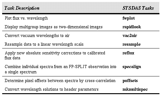
Data Reduction and Display
The tasks listed in Table 6.9 are used to display or prepare the data for further analysis.


